
Prismatic cell module and PACK assembly line
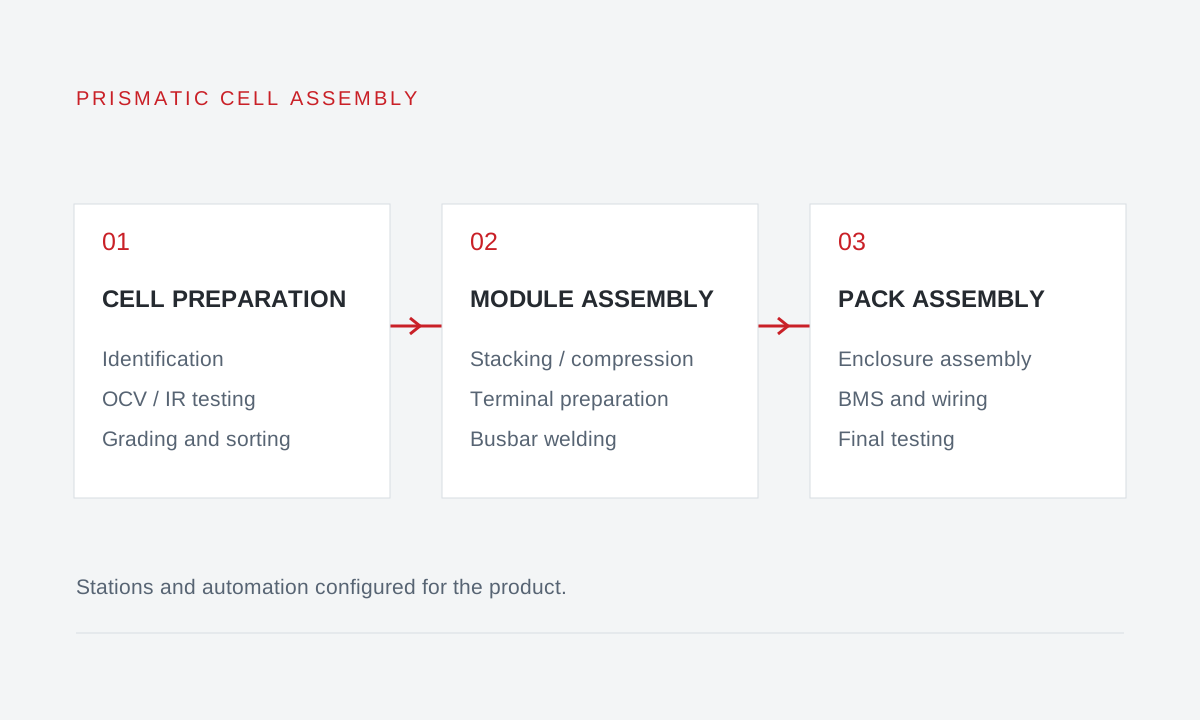
Configurable cell preparation, module assembly and PACK assembly, with identification, testing, stacking, compression, terminal processing, busbar welding and final inspection.
Applications & configuration
- The three stages can be implemented separately around existing equipment, with coordinated fixtures and data interfaces.
- Manual, semi-automatic and automated stations are combined for the product; robotic loading is optional.
- For prismatic battery assembly projects, with assembly, testing and quality records defined by the end use.
Cell preparation: linking identity and test results
Before assembly, stations can identify cells, measure open-circuit voltage (OCV) and internal resistance (IR), grade them and divert rejected cells. Test results are linked to cell IDs for grouping and traceability.
Bin counts and acceptance limits are set for the cell and product. One possible configuration has four accepted bins and one reject bin; this does not imply common thresholds across products.
Module assembly: stacking, compression and welding
Cell stacking, compression and strapping follow the module arrangement and retention method. Compression equipment may work with manual strap threading and fastening; additional automation depends on product structure and cycle time.
Vision locates terminals, laser cleaning prepares the joining surface, and busbar welding creates electrical connections. These are separate operations with distinct fixture, positioning and quality-check requirements.
PACK assembly: from modules to finished units
After modules enter the enclosure, stations handle connectors, BMS and wiring, lid assembly and final testing to the product drawings. Module manufacture and PACK assembly have different fixtures, handling loads and test objects.
Leak, insulation and end-of-line (EOL) tests are configured to product specifications, with defined interfaces, acceptance criteria and data fields. Test stations are evaluated alongside the line cycle time.
Configuration by application and production organisation
The following comparison supports equipment selection. Establish cell origin, product use and applicable requirements before selecting the assembly process; new-cell assembly and retired EV battery repurposing require separate assessments.
Waste traction batteries must not be used in e-bikes or other prohibited applications. Products for other uses must meet the quality standards of their application. Read the end-use requirements.
| Application | Key inputs | Station planning |
|---|---|---|
| Residential and commercial storage | Module configuration, enclosure interfaces, BMS and tests | Connect module and PACK stages with product-specific tests |
| Light-power and parking power supplies | Assembly dimensions, joining method, batch size and changeovers | Combine trolleys, semi-automatic and dedicated stations by batch needs |
| Multiple prismatic assembly formats | Cell geometry, terminal positions and fixture interchangeability | Define changeovers before selecting automation |
Information for line selection
Provide cell specifications, module and PACK drawings, electrical configuration, output and shifts, joining and test requirements, site dimensions and existing equipment interfaces. Equal Ah capacity does not imply identical dimensions, terminals or fixtures.
Process and selection guide
Read the process and selection guideRelated equipment & configurations
Equipment selection and line enquiries
Share your battery type, processing goals and site conditions so we can assess the process.